Instant review system for badminton: computer vision system use case


Badminton is the fastest sports game in the world. The shuttlecock can travel at a speed of over 400 km/h. The world record, measured in a laboratory in 2013, was 493 km/h. Because of such a high speed and human-eye perception, the line judges often cannot tell if the shuttlecock was in or out. A referee can judge if there was an out by analysing slow-motion video footage, but that process takes some time. The solution can be a computer vision system that allows instant review and automatically makes in/out decisions.
Our specialists were involved in creating such an instant review system for one of our clients. Our team was responsible for the computer vision module and artificial neural networks. Read the case study below to find out more about the project and its outcome.
Requirements for computer vision review system in badminton
The instant review system for badminton works as follows. The number of cameras and their location is selected, so they can see, as a minimum, all the lines and areas around them and a flying shuttlecock approaching the ground. Video streams and visual data from cameras go to computers, where our software processes them and, by analysing the shuttle trajectory, calculates where the shuttle hits the ground by comparing this spot with the court model or previously detected court lines.
A player who disagrees with the linesman’s decision raises their hand and asks the umpire for a challenge. The umpire sends the challenge request to the system operator. They then start the procedure and receive information from the system about whether the line judge has made a good decision. The operator or a designated judge may verify the system’s result and manually correct it. After verification, the system generates an animation and presents it to the players, judges, spectators, and TV broadcasters.
When designing the system, we adopted the following assumptions.
- The system should be as accurate as possible.
- The whole verification procedure should not take longer than 25s.
- The installation time should be as short as possible, no longer than 4h per court.
- The installation should not require more than two people.
- All equipment should take up as little space and weight as possible.
The main requirements for the system were:
- Video recording at 150-200 frames per second.
- System response in near real time.
- Efficient algorithms running on inexpensive PC computers.
Challenges and solutions for computer vision system applications
During the work, we encountered many challenges: from selecting the appropriate architecture and tools, through developing efficient algorithms, to integration with the live scoring system.
Camera calibration for computer vision system
The camera’s calibration is essential for precise court model fitting when 3D tracking is involved. It is crucial that the calibration process is fast and easy to perform. Figure 1 shows an original image from the camera’s footage (upper) and the same image after applying distortion coefficients calculated during the calibration process.
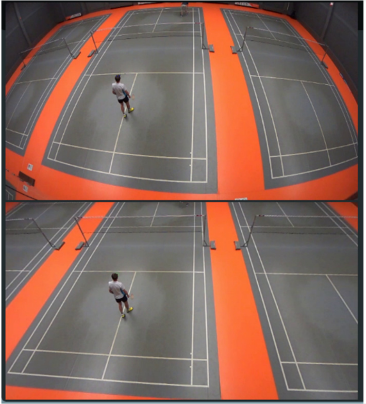
Figure 1. Instant review system badminton: The same image before and after applying calculated distortion coefficients
Because the system is mobile, the calibration must be done in a venue. We have developed special software for fast calibration. For our calibration procedure, we use a calibration board with circles. The minimum reprojection error we got was 0.086px.
Court recognition
To determine if the shuttlecock landed in or outside the court, we must first recognise it. The court recognition procedure is performed for each camera. The court’s dimensions are standardised, so it is easy to recognise the court and fit it into the model. Hough transform [1] can be applied to the Sobel filter [2] output to find court lines. Then the intersections of the lines can be detected by using the Bentley—Ottmann algorithm [3]. Another method is to use the Harris corner detector [4] to detect court corners.
Before running the court lines recognition procedure, we use a modified version of the Mask R-CNN [5] to detect and segment the court or a part of a court from the image. The masks generated by the neural network are dilated before applying them to the image to make sure that all court lines are visible. Then the Hough transform and pattern matching are applied to match the detected court with the model. We then analysed the lines and corners fitting and adjusted the model in case of inconsistencies caused by rubber court mat deformations. The accuracy of court segmentation is 97.7%.
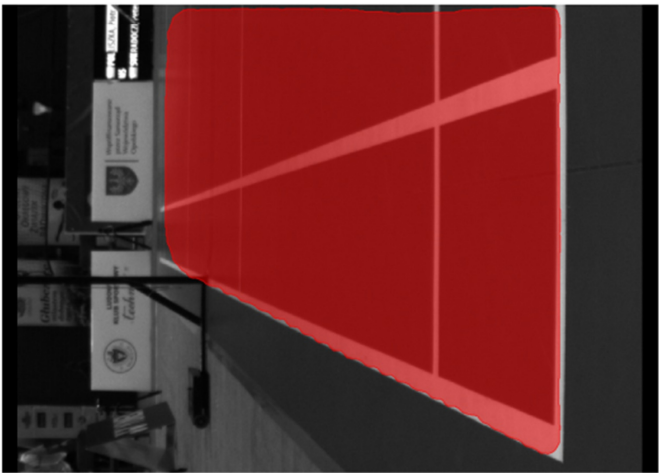
Figure 2. Court segmentation – Mask RCNN result
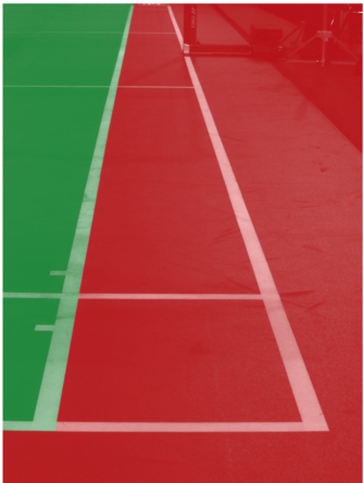
Figure 3. In (green) and out (red) of a court area after finding court lines
The speed of algorithms
Algorithms of image analysis that require a long computation time or high computational resources cannot be used. We decided to develop a hybrid solution. It uses simple and fast detection based on differential frames and only sometimes uses a neural network on patches of single frames when the first method loses the tracked object. With the single computer equipped with 9th Gen. Intel® Core™ i7-processor and GPU: NVIDIA® GTX 1080 we can process data from two cameras with a speed up to 200 FPS (resolution 800×600).
Flickering light
Algorithms based on differential frames are sensitive to flickering light. The newest and most modern sports halls are equipped with flicker-free lights, but most venues where national tournaments are played have old, flickering lights. Although many methods and commercial software remove flickering, they are unsuitable for fast video-stream processing. We concentrated on the speed with still reasonable and applicable results. We developed an adaptive pixel-wise method of generating masks that compensate for the flickering effect. Our method is 250–300 times faster than DeFlicker[6] and FlickerFree[7]. The method is described in detail in our paper [8].
We use the fact that our cameras do not move, as this allows us to calculate the similarity level of each pixel to the same pixel from the previous frame. If a pixel has changed because of a local movement in a scene, then the similarity level would be low. If similarity levels are higher than the threshold, then we interpret it as the flickering effect, which is reduced by our algorithm. The image below shows in top-right corner original frame, the top-left corner diff frame before applying the flicker removal algorithm, the bottom-left diff frame after applying the flicker removal algorithm, bottom-right original frame after applying the flicker removal algorithm.
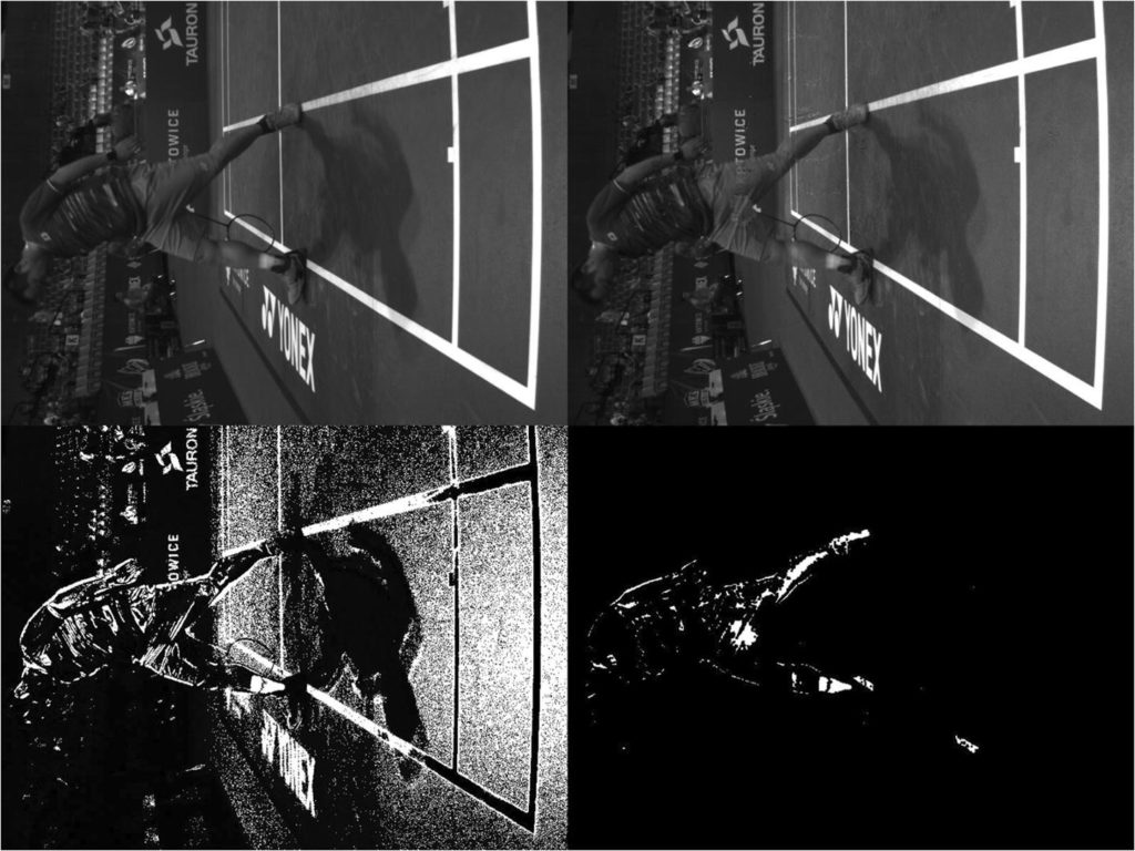
Figure 4. Diff frame before applying flicker removal algorithm – top-left corner, diff frame after applying flicker removal algorithm – bottom-left
Shuttlecock detection, tracking, segmentation
To be able to track any object, firstly, it must be found within the image. Many methods can be used for finding a specific item and object detection, from the most straightforward, such as colour and shape segmentation, to methods utilising neural networks.
The use of a generic, universal approach for shuttlecock detection is problematic because of the following:
1. Depending on the camera’s view, the badminton shuttlecock silhouette can be seen as a circle or a triangle, so finding it within the image is more complex than finding a ball.
2. The size of the shuttlecock may change significantly when it approaches the camera.
3. A shuttlecock moves at rapidly varying speeds, reaching very high values at times. The algorithm must work well with fast (400 km/h) and slow (24 km/h) shuttlecocks velocities.
4. The white colour of the shuttlecock can be very similar to the scene (player socks, white court lines, and letters on advertisement boards).
5. The shuttlecock often moves in complex contexts: moving players, fast rackets, and changing backgrounds.
6. Because of the cone-like shape and centre of gravity located next to the cork (not in the centre), it is difficult to predict the trajectory following the physics laws described by simple formulas, especially after the hit, when the shuttlecock turns over and has an unstable trajectory.
We utilise the feature that a shuttlecock is a fast-moving object over a usually still background. Differential images generated from consecutive frames allow us to distinguish moving objects from static backgrounds. On the other hand, when the shuttlecock hits the ground, it changes direction and may even stop moving for a moment and vanish from the differential image. Our solution generates an accumulative differential frame from 7 consecutive differential images. This allows us to keep sight of the shuttlecock when it hits the ground. Figure 5 shows an accumulative differential frame (a) and the direction of moving blobs marked by lines (b). The blob with the white outline in Figure 5b is the one that was recognized as a shuttlecock. Other blobs in this figure were filtered out. The colour of a blob represents the filter that filtered out the shuttlecock candidate.
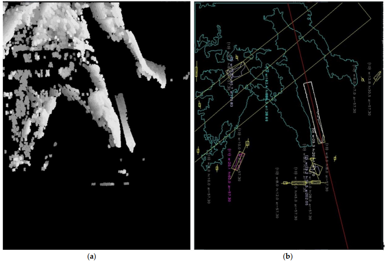
Figure 5. Computer vision system segmentation: The accumulative differential frame (a) (on the left). Blobs with marked moving direction by lines (b) (on the right).
Shape segmentation makes it easy to distinguish a shuttlecock from another moving object. The whole process takes less than 2 ms on an Intel Core i7 machine. There are situations when, behind a shuttlecock, a player is moving. The blob of a player is usually much bigger than the blob of a shuttlecock, and both blobs overlap. The segmentation algorithm may mistakenly treat the shuttlecock as a fragment of a player. To solve it, we follow the algorithm:
1. With the use of a Kalman filter [9], predict where the shuttle should be, based on the trajectory from the previous frames.
2. Generate a patch (104 × 104 px) from the original frame with the centre predicted by a Kalman filter.
3. Pass a generated patch to a neural network detector as an input
Our neural network is a modified Tiny Yolo [10] trained with a set of images collected during the tournaments. The detection of a shuttlecock with a neural network takes 12 ms and causes a delay, which is, however, acceptable. When the first method finds the shuttlecock again, it eliminates the delay caused by the neural network, and the entire algorithm works in almost-real time. The neural network with a single class (shuttlecock) achieves a mean average precision ([email protected]) of 94%, and for a threshold of 0.25 precision, it achieves 0.96, a recall of 0.77, and an F1-score of 0.86.
Tracker Performance
To evaluate the tracker performance of our computer vision system for badminton, we needed reference data. In this case, we could use data recorded in a laboratory, but we decided to use data from real tournaments. Such a method ensures that the calculated accuracy will match the accuracy of the system under real conditions. Moreover, we decided to use only recordings when the player disagrees with the line judge’s decision. Each time the player asked for verification, our system saved 30 seconds of camera footage at 150-190 fps. From recorded movies, we selected 52 sets of frames for annotation. We annotated a total of 20,788 frames.
Our tracker detects if the shuttlecock is visible with an accuracy of 94%. For the frames where the shuttlecock was visible, we measured if the detected position of a shuttlecock was correct. The detection of a shuttlecock position was marked successful if the difference between annotated position and the position saved by the detector was less than 12 pixels. 81% of the visible shuttlecocks were correctly detected and tracked.
Object segmentation for computer vision system
While the shuttlecock moves at high speed, it is blurred within the image. The motion blur effect causes segmentation difficulties due to ambiguous pixels between regions of the object and the background. Imprecise shuttlecock contour detection reduces the accuracy of localising the cork when it comes into contact with the ground, impairing the overall system accuracy.
Figure 6. Accumulated diff (yellow) together with an original image. Red circle = ground touch point. Blue arrow – movement direction
Finding the frame when the shuttlecock hits the ground
The standard approach for finding a ground hit is a trajectory change. It works well for tennis, where the ball is resilient and the bounce is high. A shuttlecock does not bounce very high, but when it hits the ground, it slows down (and even stops for a moment). However, sometimes it may slide, so the trajectory does not change significantly. The sudden change in speed is also evident in the change in the degree of blurring.
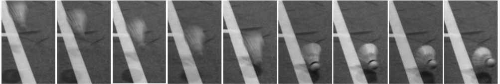
Figure 7. Shuttlecock before and after the ground touch
Figure 7 shows a set of images of a shuttlecock before and after the ground touch. As can be seen, the speed of a shuttlecock changes more significantly than the trajectory. That is why, except for using trajectory-change information, we also utilise the shuttlecock blurriness measure calculated as the variance of the Laplacian.
Results
The computer vision-based system presents the results in the form of an artificial animation. Such a solution is attractive to the audience and prevents discussions and doubts when the original camera image is blurred, or the shuttlecock is partially obscured. The examples of our challenge animations from tournaments can be seen here:
The system delivers a correct decision in 62% of cases. Even a tiny error in one of the steps of the processing pipeline, i.e., shuttlecock detection, shuttlecock tracking, ground hit frame detection, line detection, cork segmentation, and in–out decision, may lead to the wrong system’s answer. That is why, in the system, the human operator confirms the final in/out decision.
Discover more about our computer vision services
Learn more
Further work on a computer vision system for badminton
The main challenge is to improve the accuracy of the system. Accuracy can be increased by using higher-resolution cameras or increasing their number.
The capabilities of hardware available on the market change over time: The newest cameras have the same speed but much higher resolution than the ones we bought a few years ago. They are also much more expensive.
Buying better cameras is not enough because higher resolution means that our system must process much more data at the same constrained time. Increasing the computing power of computers must be combined with changes in algorithms to adapt to much larger data streams.
It should be noted that the camera’s high resolution is only needed when the shuttlecock hits the ground. A higher acquisition speed is needed to determine the moment at which the shuttlecock rebounds against the ground. A higher resolution can also be obtained by using super-resolution algorithms, which may be an element of further investigation.
Since the automatic decision of whether the shuttlecock falls in the field of play or outside of it must be presented within 10–25 s, the equipment and algorithms should be wisely selected.
Leverage the computer vision module and artificial neural networks technology
Computer vision technology together with artificial intelligence algorithms can be used for many purposes. Specific object tracking and detection is just one of them. Analysing images, video frames and visual data can help with image recognition, pattern recognition and object classification in various solutions across industries.
Your company, system, or application can take advantage of these solutions, too. Tell us about your idea – our AI experts will help you bring it to life. Visit our Artificial Intelligence and Machine Learning offering for more details about our services or contact us via form below.
FAQ
The instant review system is a computer vision-based solution that helps determine the exact landing position of a shuttlecock in badminton. It assists referees in making more accurate and objective decisions during matches. System aims to eliminate human error and enhance the overall quality of officiating in the sport.
Computer vision is central to the system, enabling it to track shuttlecock movement and determine its position on the court. High-speed cameras and image processing algorithms work together to analyse footage in real-time. This technology helps in identifying whether the shuttle landed in or out with high accuracy.
The system utilises supervised learning techniques to train models on annotated shuttlecock images. It uses object detection algorithms to locate the shuttle in video frames. These models improve over time as more training data is introduced, enhancing accuracy and response time.
Key challenges include handling the high speed and small size of the shuttlecock, as well as ensuring consistent lighting and camera calibration. Another issue is processing large amounts of video data with minimal delay. Balancing accuracy and performance is also a significant concern during system development.
The system has demonstrated high accuracy in detecting shuttlecock landings, especially in controlled environments. It relies on well-calibrated hardware and optimised algorithms to maintain precision. Continued testing and data collection further improve its reliability.
Yes, the system is specifically designed for real-time application, allowing referees to request instant reviews during play. Fast data processing and clear visual outputs make it highly effective for use in tournaments. Its response time is tuned to ensure decisions are made without interrupting the game flow.
References
- Duda, R. O. and P. E. Hart, “Use of the Hough Transformation to Detect Lines and Curves in Pictures,” Comm. ACM, Vol. 15, pp. 11–15 (January, 1972)
- Irwin Sobel, 2014, History and Definition of the Sobel Operator
- Bentley, J.L.; Ottmann, T.A. Algorithms for reporting and counting geometric intersections. IEEE Trans. Comput. 1979, C-28, 643–647.
- Chris Harris and Mike Stephens (1988). “A Combined Corner and Edge Detector”. Alvey Vision Conference. Vol. 15.
- He, K.; Gkioxari, G.; Dollár, P.; Girshick, R. Mask R-CNN. In Proceedings of the 2017 IEEE International Conference on Computer Vision (ICCV), Venice, Italy, 22–29 October 2017; pp. 2961–2969.
- DEFlicker—RE: Vision Effects. Available online: https://revisionfx.com/products/deflicker/
- Digital Anarchy’s Flicker Free Removal Software. Flicker Free Plugin: Deflicker Time Lapse, LED and Slow motion/High Frame. Available online: https://digitalanarchy.com/Flicker/main.html.
- Nowisz, J.; Kopania, M.; Przelaskowski, A. Realtime flicker removal for fast video streaming and detection of moving objects. Multimed. Tools Appl. 2021, 80, 14941–14960.
- Kalman, R.E. A New Approach to Linear Filtering and Prediction Problems. Trans. ASME—J. Basic Eng. 1960, 82, 35–45.
- Redmon, J.; Farhadi, A. YOLOv3: An Incremental Improvement. arXiv 2018, arXiv:1804.02767.
Appendix 1: worth to watch
- How the shuttle cock flips in air? Understand the science behind it
https://www.youtube.com/watch?v=kv7ypfi4nNs - How Badminton Birdies Are Made
https://www.youtube.com/watch?v=XS7HLzQZFgk - Birdie In Flight: The Science of Badminton
https://www.youtube.com/watch?v=Y4B1SoFKnBo - Badminton biomechanics: The Science of Shuttles
https://www.youtube.com/watch?v=yjrY5eglqWg


arrow_circle_rightContact us
Contact us to discuss your needs

Tomasz Smolarczyk
Director of Artificial Intelligence