Robotics lab: enhancing robotic perception through sensor fusion
The field of robotics stands at the forefront of technology, driving innovations that extend from industrial automation to autonomous vehicles and beyond. At the heart of these systems lies sophisticated software that integrates inputs from an array of sensors, including LiDAR, cameras, Inertial Measurement Units (IMUs), barometers, and GPS. These sensors provide critical data that enable robots to perceive and interact with their environment. However, the process of developing this software is fraught with challenges, particularly in terms of handling and fusing data from these diverse sources.
Each sensor offers unique advantages and introduces its own set of complexities. For instance, LiDAR excels in providing precise distance measurements, which are crucial for obstacle detection and navigation, but struggles under certain environmental conditions like rain or fog. Cameras provide rich visual information that is essential for tasks such as object recognition and scene understanding, yet they are heavily affected by varying lighting conditions. IMUs offer valuable data regarding orientation and movement, but their readings can be marred by drift over time. Barometers, which can help determine altitude by measuring atmospheric pressure, are sensitive to weather variations. Lastly, GPS units provide essential geolocation data but are often hampered by signal obstructions in urban settings or dense forests.
The role of sensor fusion
Integrating data from these sensors, known as sensor fusion, is further complicated by the need to align and synchronise data, which may have different sampling rates and varying degrees of accuracy and reliability. Achieving precise, real-time fusion of this data is crucial for the robot’s coherent and accurate understanding of its surroundings. This precise and timely integration is key to optimising the decision-making algorithms that guide the robot’s actions. Minimal delays in data processing are essential, as they ensure that the robot can respond swiftly and effectively to dynamic environmental changes. To enhance the robot’s responsiveness, sensor fusion techniques must be accurate and quick. Strategies such as parallel processing, predictive modelling, and hardware acceleration can reduce the time to fuse data and feed it into decision-making algorithms. These improvements help ensure that the robot’s actions are timely and well-informed, maximising efficiency and safety.
Let’s focus on three main challenges we encountered when building a robotic system based on input from peripheral sensors.
- The first and most general challenge is the synchronisation of devices, or more accurately, the synchronisation of sensor output data so that the main computational unit can align their data frames on a timeline.
- The next aspect is the calibration of devices, particularly those sensors that operate on a localisation plane (e.g., cameras, LiDAR) to determine the appropriate positioning of components installed in the robot, as well as the direction and spectrum of vision.
- The last, but no less important, challenge is the reduction of errors and the minimisation of sensor noise, primarily using Kalman filters and derivative algorithms.
For this article, I utilised advanced technological equipment to ensure high-quality data collection and accuracy. Specifically, I employed the Ouster OS1 3D LiDAR sensor and the See3CAM camera.
Hardware, software and sensor synchronisation
In sensor integration, precision and accuracy are paramount, particularly when deploying systems that rely on sensor fusion. Ensuring the correct synchronisation of peripheral devices through both hardware and software means is essential to achieve a robust and error-free operation.
Hardware synchronisation
Hardware synchronisation involves aligning the clocks of various sensors so that their readings are taken at the exact same time. This is critical in environments where timing discrepancies can lead to errors in data interpretation, potentially causing things like the misalignment of objects in 3D space or incorrect vehicle positioning.
Hardware synchronisation can be achieved through various methods. Some of these include:
- Common clock source: All peripheral sensors are connected to a unified clock source, ensuring synchronised data capture.
- Triggering mechanisms: Sensors can be designed to start measurements upon receiving a specific hardware signal, ensuring simultaneous data capture. The most basic mechanism operates on a simple signal and is low cost; however, it may not be sufficient for achieving complex functionality in more sophisticated communication scenarios.
- Precision Time Protocol (PTP): Used in networked devices to ensure that the clocks in each device are synchronised to a master clock. The proposed solution is quite costly for embedded devices, however it provides the greatest flexibility when upgrading sensors. The only criterion is support for the PTP protocol to maintain compatibility.
Software synchronisation
Software synchronisation handles the integration of data that wasn’t captured at the exact same moment. It compensates for differences in sensor output rates and processing times. There are many mechanisms to improve synchronisation, the main being:
- Timestamp matching: Software algorithms match data from different sensors based on the timestamps of their readings.
- Interpolation: If exact timestamp matches are not available, interpolation can be used to estimate sensor readings at specific times.
- Buffering: Storing data temporarily to wait for the slowest sensor to catch up, ensuring that data sets are complete before processing.
Other factors synchronisation
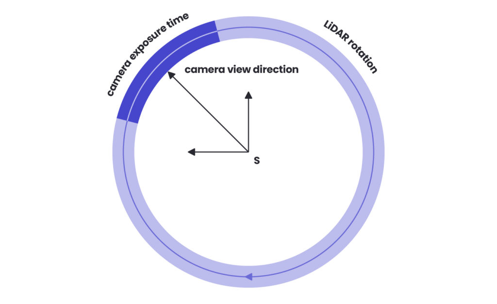
One example of additional sensor synchronisation factors is the camera’s global shutter triggering and the actual production of image data. First, the delay between triggering a camera’s global shutter and producing image data needs to be carefully managed, especially when synchronisation requires millisecond precision. Additionally, the synchronisation process must take into account the generally lower frequency of LiDAR systems compared to cameras. For LiDAR models that utilise a 360-degree rotational field, it’s also essential to align the LiDAR’s data coverage with the camera’s field of view, ensuring that the moments captured by both sensors correspond spatially and temporally for accurate data fusion.
Synchronisation 360° LiDAR with camera view:

The optimal synchronisation approach combines hardware synchronisation supplemented by software-level validation. However, synchronisation alone does not guarantee correct data processing from peripheral sensors. The key lies in a central computing unit that is sufficiently powerful, with well-balanced processor cores, to handle data processing in real time. The information processing optimisation must be tailored to match the computational loads of the algorithms operating on the input data within the ROS (Robot Operating System) environment. This careful balancing act ensures that the system not only collects data synchronously but also processes and interprets it efficiently, leading to timely and accurate decision-making capabilities in robotic systems. Furthermore, thorough testing is essential to ensure synchronisation mechanisms work correctly under all expected conditions. Continuous monitoring of the system’s synchronisation status is also crucial to detect and correct any drifts over time.
Calibration of devices for proper interaction and integration
One of the foundational aspects of sensor fusion in robotics is accurately determining the orientation of a camera relative to other sensors, such as LiDAR or an Inertial Measurement Unit (IMU). This alignment is essential, as it ensures that the system’s algorithms can accurately update measurement data when the device rotates. Proper calibration of these devices enhances their interaction and data integration, leading to more accurate performance in complex environments.
Intrinsic calibration
This initial phase involves determining the internal camera parameters, such as the focal length, optical centre, and lens distortion characteristics. Intrinsic calibration is crucial for correcting distortions in the camera’s raw image data, enabling it to accurately represent the real world as seen through the lens.
Extrinsic calibration to LiDAR or IMU
After the intrinsic calibration, extrinsic calibration is performed to establish the spatial relationship between the camera and external devices like LiDAR or IMU. This step involves calculating the rotation and translation vectors that align the camera with these sensors. Establishing this precise geometrical alignment allows the system to effectively merge and utilise data from diverse sensory inputs, enhancing the overall functionality and accuracy of the robotic system.
Challenges in camera-LiDAR calibration
Calibrating a camera to align with LiDAR data is notably challenging. The camera’s lens must accurately capture the same scene elements that the LiDAR scans. A significant obstacle in this process is ensuring that distinctive features in the scene, crucial for image detection, have a consistent structure to facilitate stable reproducibility. Due to potential variability in these features, calibrating the camera with an IMU integrated with the LiDAR is often more effective. This approach involves moving the assembly containing the IMU, camera, and LiDAR across different positions while recording specific ArUco markers. This technique leverages motion-induced data from the IMU to refine the alignment between the camera and LiDAR, ultimately enhancing the precision and effectiveness of the sensor fusion.
Use case: Spyrosoft’s R&D project
Dojo is our robotics R&D programme – a space where we create projects dictated by business and technology needs. We carry out initiatives that arise from market demands, that are also interesting for us – Spyrosoft people – and boost our competencies.
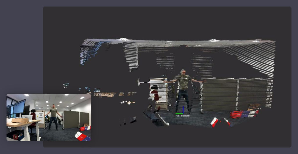
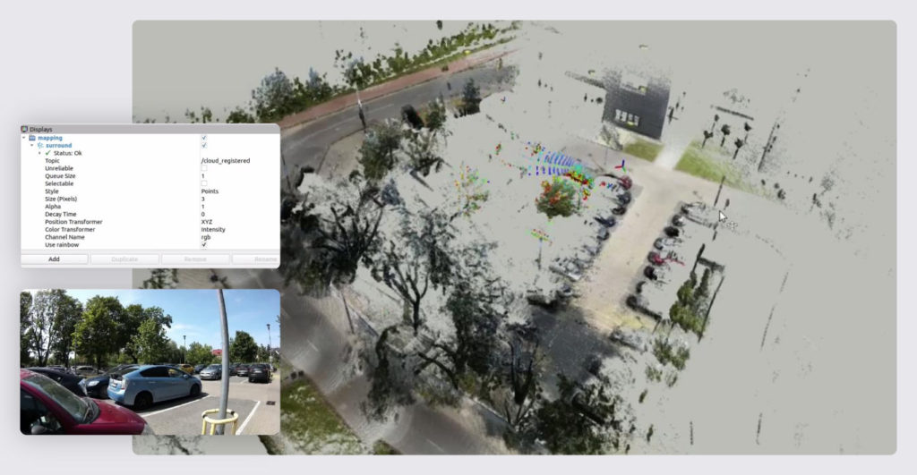
Recently, we worked on solving a sensor fusion challenge within one of our Dojo initiatives.


Each of these sensors has its own noise characteristics, which can be due to various factors, including sensor quality, environmental conditions, and operational constraints. Noise can manifest as random fluctuations or systematic errors in sensor readings, leading to inaccurate data and potentially compromising the overall system performance.
Here, the Kalman filter algorithm plays a critical role in addressing these challenges within sensor fusion frameworks. It provides an optimal estimation of the internal states of a linear dynamic system from a series of incomplete and noisy measurements, making it particularly effective for enhancing sensor data reliability.
The operation of the Kalman filter is characterised by two primary phases: prediction and update. During the prediction phase, the filter utilises a mathematical model of the system to forecast the next state and assesses the uncertainty associated with this prediction. This phase prepares the system to anticipate future states based on the current data trends and model dynamics. In the subsequent update phase, the filter incorporates a new measurement and recalibrates the predicted state towards this latest measurement. The adjustment is weighted by the reliability of the new data and the predicted uncertainty. This mechanism allows the filter to refine its estimates continuously and reduce the impact of any individual measurement’s noise or error. The Kalman filter excels in environments where noise distributions are Gaussian. It effectively minimises noise impact by averaging the predicted state and the actual measurements, applying weights based on their respective uncertainties. This method ensures that the system maintains a balanced and realistic representation of the state based on both historical data and new information.
If sensors continue to produce data that lacks sufficient accuracy even after proper synchronisation and calibration, Kalman filters can be used to eliminate noise and smooth out fluctuations between sampling points. A significant advantage of the Kalman filter in sensor fusion is its ability to integrate disparate sensors’ measurements, accommodating their unique noise characteristics and accuracies. For instance, it can merge the high-frequency, low-latency data from an IMU with the high-accuracy, but slower, data from a GPS. This integration is critical in applications requiring precise navigation and timing, such as autonomous vehicles and mobile robotics, where sensors must work in concert to provide reliable and up-to-date situational awareness.
To sum up
Successfully overcoming the challenges of synchronisation, calibration, and noise reduction is crucial for optimising robotic systems that rely on complex sensor fusion.
Synchronisation ensures that data from various sensors is aligned temporally and spatially, which is fundamental for the system to function coherently in real-time environments.
Calibration, particularly between different sensor types like cameras and LiDAR, enhances the precision of data interpretation, allowing for more accurate and reliable navigation and task execution.
Lastly, implementing noise-reducing techniques such as Kalman filters is essential for minimising the impact of sensor inaccuracies and ensuring the system’s robustness against external disturbances and inherent sensor flaws.
These combined efforts not only improve the reliability and functionality of robots but also enable more advanced applications and greater autonomy in operational tasks. By continuously refining these processes and integrating cutting-edge algorithms, robotic systems can achieve higher levels of performance and adaptability, paving the way for future innovations in automation and artificial intelligence.
Are you looking for robotics specialists?
Learn how we can support your next product – check our Robotics services, and don’t hesitate to get in touch if case of any questions.
About the author
Contact us
Transform your industry with robotics solutions. Contact our expert to find out more
RECOMMENDED ARTICLES


![[bloghero-thumbnail] ros on nvidia jetson board](https://spyro-soft.com/wp-content/uploads/2023/07/bloghero-thumbnail-ros-on-nvidia-jetson-board.jpg)